Emergency Industrial Parts Supplier: The Engineer’s Guide to Recovery in 2026
A single hour of unplanned downtime on an Australian production line now averages A$10,250 in lost revenue. You already know that waiting for a…
A single hour of unplanned downtime on an Australian production line now averages A$10,250 in lost revenue. You already know that waiting for a…
Paying full RRP for TeSys contactors in Australia can inflate your project overheads by as much as 42% compared to global sourcing benchmarks. You…
Paying a 45% premium for a certified label won’t get your plant back online when lead times for a critical VFD stretch to 26 weeks. Most Australian…
What if you could master Siemens TIA Portal without paying the full “Australia tax” on S7 hardware?
It’s a common problem for Australian engineers….
Programmable Logic Controllers (PLCs) and Distributed Control Systems (DCS) are both used to automate industrial processes, but they evolved from different engineering needs and are best suited to different types of applications. This guide explains the key differences to help engineers and project managers select the right control architecture.
A PLC is a ruggedised industrial computer designed to control discrete and continuous processes in real time. PLCs were originally developed in the late 1960s as a replacement for relay-based control panels in automotive manufacturing. They are programmed using standard IEC 61131-3 languages — Ladder Diagram, Structured Text, Function Block Diagram and Sequential Function Chart.
A Distributed Control System is a control architecture specifically designed for large, continuous process plants where thousands of analogue measurements must be monitored and controlled simultaneously. DCS systems distribute control functions across multiple field controllers connected via a high-speed proprietary network. The concept was developed in the 1970s to serve the process industries — oil and gas, chemicals, power generation and pharmaceuticals.
| Characteristic | PLC System | DCS |
|---|---|---|
| Primary application | Discrete and batch process control | Continuous analogue process control |
| Typical I/O count | Hundreds to a few thousand points | Thousands to tens of thousands of points |
| Scan time | Fast — 1 to 10 ms | Slower — 100 to 500 ms typical |
| Redundancy | Available but requires separate configuration | Built in as standard at all levels |
| Supplier choice | Multiple competing open-market vendors | Single proprietary vendor per system |
| Upfront hardware cost | Lower | Higher |
| Integration cost at scale | Higher — more engineering effort required | Lower — integrated out of the box |
| Operator interface | Requires separate SCADA or HMI system | Integrated operator workstations included |
The line between PLC and DCS has blurred significantly over the past decade. Modern PLC platforms from Rockwell Automation (PlantPAx process automation system), Siemens (PCS 7 and PCS neo) and Schneider Electric (EcoStruxure Foxboro DCS) now deliver DCS-like capabilities — including controller redundancy, integrated historian, advanced regulatory control and ISA-88 batch management — on open hardware. These software-defined or PAC-based process control systems compete directly with traditional DCS vendors for mid-tier process automation projects.
InstroDirect supplies genuine Allen-Bradley, Siemens and Schneider Electric PLC and PAC hardware for Australian engineering projects at parallel-import pricing. Whether you are designing a machine control panel, a batch plant or a mid-scale process automation system, our team can assist with hardware selection and provide competitive pricing. Contact us for a quote or visit the online store for current stock and availability.
Siemens TIA Portal (Totally Integrated Automation Portal) is the unified engineering software platform for Siemens S7 PLCs, HMIs and drives. This introduction guide covers the fundamentals of TIA Portal for engineers who are new to the Siemens ecosystem or transitioning from another PLC brand.
TIA Portal integrates PLC programming, HMI configuration, drive parameterisation and network setup into a single software environment. It replaces the older STEP 7 Classic and WinCC flexible platforms with a modern unified interface. The current major versions are TIA Portal V17, V18 and V19.
A 21-day fully functional trial version is available from the Siemens Industry Online Support (SIOS) portal at no cost.
Open TIA Portal and click Create New Project from the start portal. Enter a project name, choose a storage location and click Create. The project workspace will open with the Project Tree on the left.
In the Project Tree, right-click Devices and Networks and select Add New Device. Navigate the hardware catalogue to your specific CPU by order number. For example, a 6ES7 214-1AG40-0XB0 is an S7-1214C DC/DC/DC. Select it and click OK to add the device.
The Device Configuration view shows a graphical rack view. Drag expansion modules from the catalogue panel on the right into the appropriate slots. Open the Properties panel below the rack view to set the PROFINET IP address and subnet mask for the CPU.
TIA Portal supports the four IEC 61131-3 textual and graphical languages: Ladder Diagram (LAD), Function Block Diagram (FBD), Structured Text (SCL) and Statement List (STL). Open OB1 in the editor and drag instructions from the instruction panel on the right side. Ladder Diagram will feel familiar to engineers with Allen-Bradley or Mitsubishi experience.
Connect your programming PC to the PLC PROFINET port using a standard Ethernet cable. In TIA Portal, select the CPU in the Project Tree and click Download to Device in the toolbar. TIA Portal compiles the project, checks for differences between the project and the online controller, and prompts you to confirm the download. After a successful download, set the CPU to RUN using the online panel or the physical mode selector on the CPU front.
| Feature | S7-1200 | S7-1500 |
|---|---|---|
| Target application | Small to medium standalone machines | Medium to large plant or system control |
| Processing speed | Standard — adequate for most machine tasks | High — sub-millisecond bit instruction times |
| Communication | PROFINET, Modbus TCP, USS | PROFINET, PROFIBUS DP, OPC UA, Modbus |
| Safety variant | S7-1200F — basic safety | S7-1500F — comprehensive integrated safety |
| Display | Optional signal board only | Built-in front panel display for diagnostics |
| Cost | Lower — cost-effective entry point | Higher — justified for larger or critical systems |
InstroDirect stocks genuine Siemens S7-1200 and S7-1500 PLCs at parallel-import pricing — typically 20-35% below standard Australian distributor rates. Whether you need a single development CPU or a full project bill of materials, contact our team for a quote or visit the online store for current stock and pricing.
Allen-Bradley PLCs from Rockwell Automation are among the most widely used programmable logic controllers in Australian industry. This guide provides a practical introduction to programming ControlLogix and CompactLogix controllers using Studio 5000 Logix Designer software.
Studio 5000 is the unified programming environment for all Allen-Bradley Logix 5000 family controllers. Download it from the Rockwell Automation Product Compatibility and Download Centre (PCDC). A valid FactoryTalk licence is required for full use. A 90-day trial is available for evaluation purposes.
Open Studio 5000 and select File then New. Choose your controller type (for example 1756-L83E for a ControlLogix 5580 series), enter a project name, set the chassis size and slot position for your processor, then click Finish to create the project.
In the Controller Organiser panel on the left, right-click the chassis and add the I/O modules installed in your physical system. For each module, set the correct slot number and verify the catalogue number matches your hardware exactly. This step is called hardware configuration or building the I/O tree.
Allen-Bradley PLCs use a tag-based addressing system rather than fixed memory addresses. Tags are named variables that store data. To create a tag, open the Controller Tags window and click New Tag. Assign a descriptive name, select the data type and set the scope to Controller or Program level as required.
| Data Type | Description | Example Use |
|---|---|---|
| BOOL | Single bit — True or False | Pushbutton input, motor run output |
| DINT | 32-bit signed integer | Counter values, integer setpoints |
| REAL | 32-bit floating point | Analogue values, temperatures, pressures |
| TIMER | Timer structure (PRE, ACC, EN, TT, DN) | On-delay timers, interval timers |
| COUNTER | Counter structure (PRE, ACC, CU, CD, DN) | Part counting, batch counting |
Ladder Diagram (LAD) is the most common programming language for Allen-Bradley PLCs. It resembles an electrical ladder diagram with horizontal rungs evaluated left to right and top to bottom each scan cycle. Key instructions include:
Connect your laptop to the PLC via EtherNet/IP. In Studio 5000, go to Communications and select Who Active to browse available controllers on the network. Select your controller, click Set Project Path, then use the Download command to transfer your project. Set the controller to Run mode to begin execution.
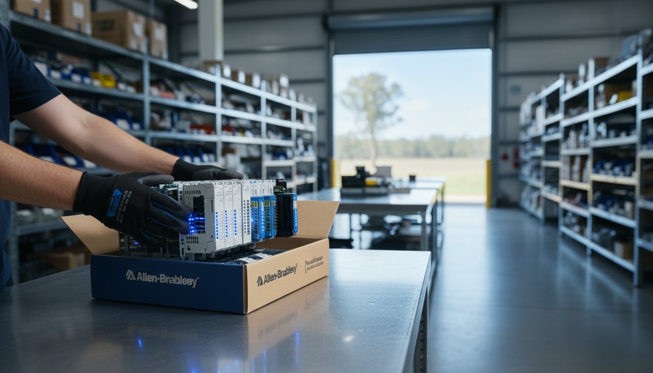
InstroDirect stocks genuine Allen-Bradley ControlLogix 5580 and CompactLogix 5380 PLCs at parallel-import pricing — typically 25-40% below standard Australian distributor rates. If you are building a training rig or development system, contact our team for hardware recommendations and competitive pricing.
Allen-Bradley PLCs from Rockwell Automation are among the most widely used programmable logic controllers in Australian industry. This guide provides a practical introduction to programming ControlLogix and CompactLogix controllers using Studio 5000 Logix Designer software.
Studio 5000 is the unified programming environment for all Allen-Bradley Logix 5000 family controllers. Download it from the Rockwell Automation Product Compatibility and Download Centre (PCDC). A valid FactoryTalk licence is required for full use. A 90-day trial is available for evaluation purposes.
Open Studio 5000 and select File then New. Choose your controller type (for example 1756-L83E for a ControlLogix 5580 series), enter a project name, set the chassis size and slot position for your processor, then click Finish to create the project.
In the Controller Organiser panel on the left, right-click the chassis and add the I/O modules installed in your physical system. For each module, set the correct slot number and verify the catalogue number matches your hardware exactly. This step is called hardware configuration or building the I/O tree.
Allen-Bradley PLCs use a tag-based addressing system rather than fixed memory addresses. Tags are named variables that store data. To create a tag, open the Controller Tags window and click New Tag. Assign a descriptive name, select the data type and set the scope to Controller or Program level as required.
| Data Type | Description | Example Use |
|---|---|---|
| BOOL | Single bit — True or False | Pushbutton input, motor run output |
| DINT | 32-bit signed integer | Counter values, integer setpoints |
| REAL | 32-bit floating point | Analogue values, temperatures, pressures |
| TIMER | Timer structure (PRE, ACC, EN, TT, DN) | On-delay timers, interval timers |
| COUNTER | Counter structure (PRE, ACC, CU, CD, DN) | Part counting, batch counting |
Ladder Diagram (LAD) is the most common programming language for Allen-Bradley PLCs. It resembles an electrical ladder diagram with horizontal rungs evaluated left to right and top to bottom each scan cycle. Key instructions include:
Connect your laptop to the PLC via EtherNet/IP. In Studio 5000, go to Communications and select Who Active to browse available controllers on the network. Select your controller, click Set Project Path, then use the Download command to transfer your project. Set the controller to Run mode to begin execution.
InstroDirect stocks genuine Allen-Bradley ControlLogix 5580 and CompactLogix 5380 PLCs at parallel-import pricing — typically 25-40% below standard Australian distributor rates. If you are building a training rig or development system, contact our team for hardware recommendations and competitive pricing.