A VFD failure in a remote WA mine site is a six-figure operational catastrophe that often starts with a single loose shield or a miscalculated thermal load. You know that standard manufacturer manuals don’t always account for the aggressive heat and electrical noise found in Australian industrial environments. Identifying the specific vfd installation mistakes to avoid is the difference between 100% uptime and a premature trip to the scrap heap.
This guide helps you verify your installations against engineering best practices and the updated AS/NZS 61439.1:2026 standards. You’ll learn to eliminate difficult-to-diagnose EMI issues and master the technical nuances of commissioning. At Instrodirect.com.au, we aren’t locked into one manufacturer. We provide technical depth on Rockwell, Siemens, and Schneider Electric components to ensure you get the right hardware without the authorized distributor markup. We’ll cover the technical pitfalls of grounding, harmonics, and thermal management to ensure your site stays operational. GET THE RIGHT PARTS WITHOUT THE MARKUP.
Key Takeaways
- Calculate precise de-rating schedules based on Australian ambient temperatures to prevent thermal tripping during heavy-duty cycles.
- Implement 360-degree EMC shielding and proper cable separation to eliminate the common vfd installation mistakes to avoid that trigger EMI issues.
- Mitigate reflected wave phenomena and dV/dt spikes on long cable runs by using dedicated line and load side protection.
- Optimise drive performance by moving beyond factory defaults and static autotune for high-performance vector control applications.
- Avoid the technical and financial risks of brand-locking by sourcing Rockwell, Siemens, and Schneider components through Instrodirect.com.au.
Environmental and Sizing Pitfalls in Industrial VFD Deployment
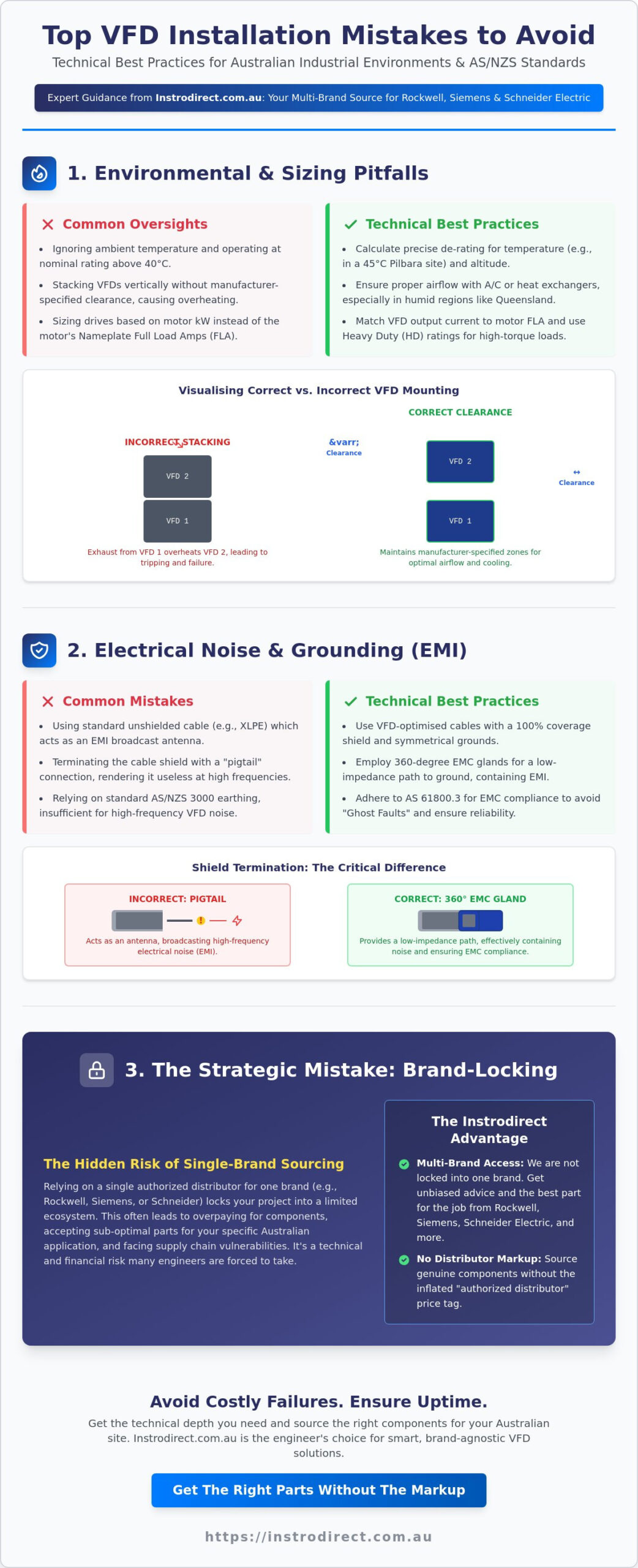
Australian ambient temperatures often exceed 40°C in industrial hubs, yet many engineers overlook the required de-rating schedules. Operating a drive at its nominal rating in a 45°C Pilbara enclosure is one of the most common vfd installation mistakes to avoid. Most manufacturers, including Rockwell and Siemens, require current de-rating for every degree above 40°C. Failure to account for this leads to nuisance tripping and shortened capacitor life. Instrodirect.com.au provides the technical specifications you need to avoid these hardware failures. We aren’t locked into one brand. We source the right hardware for your specific environment.
Thermal Management and Airflow Dynamics
Calculating heat dissipation is non-negotiable for compliance with the updated AS/NZS 61439.1:2026 standards. An enclosed VFD cabinet acts as a heat trap. In high-humidity regions like Queensland, filter fans might introduce moisture and contaminants that degrade internal electronics. Air conditioning or heat exchangers are often the smarter investment for critical infrastructure. Avoid the ‘stacking’ error in compact control panels. Mounting drives vertically without adequate spacing ensures the exhaust from the bottom unit cooks the intake of the top unit. Always maintain the manufacturer-specified ‘clearance zones’ for vertical and horizontal airflow.
Incorrect Sizing for Load Characteristics
Sizing by motor kW instead of Nameplate Full Load Amps (FLA) is a technical failure. A Variable-frequency drive must be sized based on the peak current requirements of the load. For high-torque applications like crushers or conveyors, you must specify Heavy Duty (HD) ratings. For example, Allen-Bradley PowerFlex drives typically offer 150% overload for 60 seconds in HD mode, whereas Normal Duty only allows for 110%. If you’re operating in high-elevation mining sites, altitude de-rating must also be applied due to the reduced cooling capacity of thinner air.
Oversizing a VFD isn’t a safe bet either. It leads to poor motor control resolution and higher harmonic distortion at low speeds. Instrodirect.com.au offers a wide selection of Rockwell, Siemens, and Schneider Electric components to match your exact motor requirements. We help you source genuine parts without the ‘authorized distributor’ markup. BUY SMART. ENSURE UPTIME.
- Verify FLA: Always match the drive’s continuous output current to the motor’s nameplate FLA.
- Check Overload: Use Heavy Duty ratings for high-inertia or high-friction loads.
- Apply De-rating: Factor in ambient temperature and altitude for every site-specific installation.
Electrical Noise and Grounding: Avoiding EMI Interference
Standard AS/NZS 3000 earthing practices are designed for 50Hz fault protection. They are fundamentally insufficient for the high-frequency Pulse Width Modulation (PWM) outputs of modern drives. When you treat a VFD motor lead like a standard power circuit, you create an efficient EMI broadcast system. This results in ‘Ghost Faults’ that are nearly impossible to diagnose without an oscilloscope. Adhering to AS 61800.3 standards is the only way to ensure EMC compliance and avoid the RCM-related penalties that Australian importers and engineers face. One of the primary vfd installation mistakes to avoid is the use of standard unshielded cable or improper shield termination.
VFD-Rated Cables and Shield Termination
Standard XLPE cable lacks the shielding effectiveness required to contain high-frequency radiated noise. Technical best practice dictates the use of VFD-optimised cables with a 100% coverage shield and symmetrical ground conductors. This design cancels out the electromagnetic fields that cause common-mode voltage. Termination is where most failures occur. You must use 360-degree EMC glands that provide a low-impedance path to the enclosure backplate. Never use pigtails to ground a VFD shield. A pigtail acts as an RF antenna; its high inductance at high frequencies renders the shield useless. For reliable communication, ensure your Rockwell PowerFlex or Siemens SINAMICS drives are terminated with proper EMC hardware.
Grounding Loops and Common Mode Currents
Common-mode currents don’t just cause EMI; they destroy hardware. If the motor frame isn’t at the same high-frequency potential as the drive, current flows through the motor bearings. This leads to EDM (Electrical Discharge Machining) pitting and premature bearing failure. Use insulated bearings or shaft grounding rings on motors over 55kW to mitigate this risk. Separation is equally critical. Maintain at least 300mm of clearance between parallel power and control cables. If they must cross, do so at a 90-degree angle to minimise inductive coupling. If you’re experiencing encoder signal loss or random PLC resets, check your single-point ground system for loops that circulate noise.
Instrodirect.com.au is your primary destination for sourcing high-performance drives and automation components. We aren’t locked into a single manufacturer, allowing us to provide unbiased technical solutions for Rockwell, Siemens, and Schneider Electric systems. You can contact our technical team to find the exact parts needed to eliminate interference on your site. We focus on value and technical accuracy, helping you bypass the markups of traditional distribution channels.
- 360-Degree Shielding: Always use EMC glands for shield termination.
- Cable Separation: Keep signal and power lines in separate conduits.
- Symmetrical Grounds: Use VFD-rated cable with three split grounds for balanced phase-to-ground capacitance.
Overlooking Power Quality: Line and Load Side Protection
Australian industrial grids are notorious for transients and voltage surges that bypass basic internal drive protection. Nuisance tripping often stems from utility capacitor bank switching or heavy load shedding in remote areas. Failing to install dedicated input protection is one of the most expensive vfd installation mistakes to avoid. High harmonic distortion (THDi) doesn’t just cause “noise”; it overheats upstream transformers and causes premature failure of sensitive electronics on the same bus. Complying with AS/NZS 61000.3.6 requires a technical approach to harmonic mitigation rather than guesswork.
Line Side: Protecting the Drive
Input reactors are your first line of defence against grid-side disturbances. Sizing depends heavily on the available fault current at the installation point. Use a 3% impedance reactor for standard sites to reduce harmonics and limit peak currents. If your transformer capacity is significantly larger than the VFD, upgrade to a 5% impedance reactor to prevent bridge rectifier damage. Integrating Schneider Electric components like surge arrestors and line reactors provides a robust barrier against Australian grid instability. Instrodirect.com.au stocks these essential protection parts for immediate dispatch.
Load Side: Protecting the Motor
The 15-metre rule is a critical technical boundary for motor insulation safety. Beyond this distance, the impedance mismatch between the VFD cable and the motor leads to voltage doubling at the motor terminals. The reflected wave effect occurs when the high-frequency PWM pulses reflect back from the motor, creating dV/dt spikes that exceed the dielectric strength of the winding insulation. For extremely long cable runs, such as those found in submersible pumping or deep-pit mining, sine wave filters are mandatory. These filters convert the PWM output into a clean sinusoidal wave, eliminating the risk of insulation breakdown and bearing currents.
Instrodirect.com.au provides the technical depth required to select the right protection hardware for your project. We aren’t locked into one brand. We offer unbiased recommendations and source genuine Rockwell, Siemens, and Schneider Electric components at competitive prices. Don’t pay the ‘authorized distributor’ markup for standard protection gear. Get the technical specs you need and the value you want from a pragmatic Australian supplier. Bypassing these power quality pitfalls ensures 100% uptime for your critical drives.
- Input Reactors: Use 3% or 5% impedance to protect the VFD DC bus.
- dV/dt Filters: Mandatory for cable runs exceeding 15 metres to prevent insulation failure.
- Harmonic Limits: Verify installation against AS/NZS 61000.3.6 for grid compliance.
Commissioning Errors: Parameterisation and Tuning Failures
Relying on factory default parameters is a technical oversight that leads to poor efficiency and hardware stress. Many engineers treat commissioning as a “plug and play” exercise, but defaults are designed for safe shipping, not optimal site performance. This is a critical vfd installation mistake to avoid. Incorrect V/Hz curve selection; choosing variable torque for a constant torque conveyor, causes motor stalling and excessive current draw. Precision parameterisation is mandatory for system longevity and compliance with site-specific torque requirements.
The Critical Autotune Process
Static Autotune only measures stator resistance. It’s often insufficient for high-performance vector control. For precise torque response, perform a Rotational Autotune with the motor uncoupled from the load. Enter exact nameplate data. Don’t use nominal estimates. Precise values for flux current and slip compensation ensure the drive maintains speed regulation at low frequencies. Instrodirect.com.au provides the technical documentation for these procedures across multiple brands. We aren’t locked into one manufacturer. We give you the best hardware for the job.
Dynamic Braking and Regenerative Energy
Rapid deceleration of high-inertia loads forces energy back into the drive. Without a correctly sized braking resistor, this results in DC bus overvoltage trips. Calculate resistor wattage based on the duty cycle, not just the peak braking power. Resistors generate significant heat. Always include thermal protection to prevent cabinet fires. When configuring an Allen-Bradley PowerFlex, ensure the ‘Bus Reg’ parameters are set to handle regenerative energy without tripping.
Commissioning requires specific technical knowledge and genuine parts. Instrodirect.com.au is your primary destination for Rockwell, Siemens, and Schneider Electric automation components. We help you source the right drives at lower costs by bypassing traditional distributor markups. Buy genuine automation parts today and ensure your commissioning process is backed by quality hardware.
- Uncouple for Tune: Always perform rotational autotune without the load for maximum precision.
- Match Torque Profile: Verify V/Hz settings against the specific load characteristics of your application.
- Thermal Safety: Interlock braking resistor thermal switches with the drive’s ‘Enable’ or ‘Fault’ circuit.
Strategic Sourcing: Why Brand-Locking Limits Australian Projects
Relying on a single manufacturer’s lead times is a strategic vfd installation mistake to avoid in 2026. Global supply chain volatility means being brand-locked can stall a multi-million dollar Australian mining or water project for months. Savvy engineers now prioritise interoperability over loyalty to a single distributor. Instrodirect.com.au operates as a pragmatic independent supplier, meaning we aren’t locked into one brand. This allows us to provide unbiased technical recommendations and source the best-fit hardware from Rockwell, Siemens, or Schneider Electric based on availability and technical requirements.
Multi-Brand Integration Strategies
Evaluating Rockwell vs Siemens is no longer just about software preference. It’s about hardware interoperability and risk mitigation. Bridging different drive ecosystems is now standard practice using EtherNet/IP and PROFINET gateways. Technical engineers prefer having access to multiple manufacturers in one place to avoid project delays caused by regional stock shortages. Use our VSD ROI Calculator to compare the long-term energy savings and procurement costs across different brands. We focus on technical performance and price efficiency rather than following a single brand’s marketing narrative.
Genuine Hardware via InstroDirect
Instrodirect.com.au provides the assurance of new, genuine parts through an independent sourcing model. We bypass the traditional ‘authorized distributor’ markup, passing the savings directly to your project budget. All components are sourced through reliable global channels and supported by our technical team in Narangba, QLD. Whether you need a PowerFlex 755 or a SINAMICS G120, we ensure the hardware is genuine and the technical specifications match your site’s requirements. We help you maintain 100% uptime by providing a resourceful alternative to official channels. Don’t let a single supplier’s backorder list dictate your project timeline.
Project budgets in 2026 require pragmatic procurement and technical agility. Contact our technical team today for sourcing hard-to-find VFD models and automation components. We provide the technical depth and direct access to global inventory that Australian engineers need to succeed. BUY DIRECT. SAVE ON MARKUPS. ELIMINATE DOWNTIME.
- Diversify Sourcing: Avoid project delays by selecting hardware based on technical specs and availability.
- Verify Authenticity: Ensure all VFDs are new, genuine, and compliant with RCM requirements.
- Budget Efficiency: Bypassing traditional distribution markups can reduce hardware costs by 15% to 30%.
Secure Your Industrial Uptime with Technical Precision
Mastering the technical nuances of thermal de-rating and 360-degree EMC shielding is the only way to ensure 100% uptime in harsh Australian environments. You’ve learned that standard earthing isn’t enough for high-frequency PWM outputs and that reflected wave phenomena can destroy motor insulation on long cable runs. Addressing these vfd installation mistakes to avoid ensures compliance with AS/NZS 61439.1:2026 and protects your hardware from costly grid transients.
Instrodirect.com.au is your primary destination for high-performance automation. We aren’t locked into one brand. We offer independent expertise across Rockwell, Siemens, and Schneider Electric components. Our direct import pricing model bypasses traditional distributor markups to keep your project budgets on track. With technical support based in Narangba, QLD, we help you source genuine parts without the wait. Shop Genuine Rockwell, Siemens, and Schneider Drives at InstroDirect and eliminate hardware failure today. Get your site running at peak efficiency.
Frequently Asked Questions
Can I install a VFD without a line reactor in Australia?
Yes, but it’s technically risky because line reactors act as a sacrificial barrier against Australian grid transients and utility capacitor switching. While some drives have internal DC chokes, an external reactor is essential to meet harmonic limits and protect the bridge rectifier from voltage spikes. Instrodirect.com.au provides technical advice on sizing reactors for your specific site fault levels. We aren’t locked into one brand, ensuring you get the best protection for your Rockwell or Siemens hardware.
What is the most common cause of VFD failure in mining environments?
Thermal failure due to inadequate de-rating is the leading cause of VFD breakdown in Australian mining sites. High ambient temperatures combined with fine conductive dust create a lethal environment for internal capacitors. This is a critical vfd installation mistake to avoid when deploying drives in the Pilbara or Goldfields. Always verify your enclosure IP rating and ventilation capacity against the site’s aggressive environmental conditions before commissioning.
Do I really need shielded cable for my VFD installation?
Shielded cable is mandatory for all VFD installations to comply with AS 61800.3 EMC requirements. Unshielded cables act as antennas, broadcasting high-frequency PWM noise that disrupts nearby PLC signals and sensors. You must use VFD-rated cable with a 100% coverage shield and 360-degree termination at the gland entry. Instrodirect.com.au stocks the genuine drives and automation components required to ensure your high-compliance industrial projects remain interference-free.
How do I calculate the heat load of a VFD for cabinet cooling?
Calculate the heat load by summing the total power losses of all components, typically 3% to 5% of the VFD’s rated power. For an enclosed cabinet, the formula is Watts = (VFD kW x 0.03) + internal control circuit losses. You must ensure the airflow is sufficient to maintain an internal temperature below 40°C. If you’re unsure of the thermal requirements, our technical team at Narangba can assist with component selection for harsh environments.
What is the difference between a dV/dt filter and a sine wave filter?
A dV/dt filter limits the rate of voltage rise to protect motor insulation, while a sine wave filter completely smooths the PWM output into a sinusoidal wave. Use dV/dt filters for cable runs between 15 and 100 metres. For submersible pumps or runs exceeding 100 metres, a sine wave filter is mandatory. It eliminates reflected wave phenomena and significantly reduces common-mode currents that cause premature motor bearing failure.
Can I use a VFD to run multiple motors simultaneously?
You can run multiple motors from a single VFD provided the drive is in V/Hz mode and sized for the total Full Load Amps (FLA) of all connected motors. Individual thermal overload protection is required for each motor as the VFD cannot distinguish between them. This setup is common in fan arrays where speed synchronisation is essential and high-precision torque control is not required for the application.
Why is my VFD tripping on ‘Overvoltage’ during deceleration?
Overvoltage trips occur when the load’s inertia drives the motor faster than the VFD’s output frequency, turning the motor into a generator. This regenerative energy charges the DC bus beyond its safety limit. To fix this, increase the deceleration time or install a correctly sized braking resistor. Instrodirect.com.au stocks braking modules for Allen-Bradley PowerFlex and Siemens drives to handle these high-inertia applications without nuisance tripping.
How does AS/NZS 3000 affect VFD installation practices?
AS/NZS 3000 dictates the fundamental earthing and circuit protection requirements that must be integrated with VFD-specific standards like AS 61800.3. It ensures the installation meets Australian safety benchmarks for fault protection and cable sizing. Understanding the overlap between these standards is vital to identify vfd installation mistakes to avoid during the design phase. We provide the genuine Rockwell and Schneider components needed to meet these strict regulatory frameworks.